Routing Information Protocol
Routing Information Protocol (RIP) is a dynamic routing protocol used in local and wide area networks. It uses the hop count as a routing metric to find the best path between the source and the destination network. RIP is classified as an Interior Gateway Protocol (IGP), designed for exchanging routing information within an autonomous system.
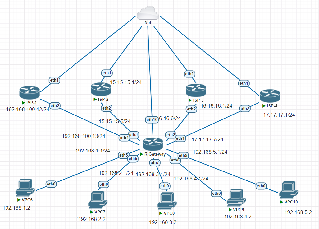
TOPOLOGY

In this context, we will conduct a simulation. This simulation involves creating four routers and four PCs. The objective is to demonstrate how the Routing Information Protocol (RIP) functions in a network. This simulation will provide a better understanding of how this dynamic routing protocol finds the best path between the origin and destination networks by using hop count as a routing metric.
Configuration R1
The following section provides a detailed breakdown of the configuration for one of the routers, R1.
[admin@MikroTik] > system identity set name=R1
The above command sets the system identity to R1.
[admin@R1] > ip address add address=12.12.12.1/24 interface=ether1
These commands are used to add IP addresses to the respective interfaces.
[admin@R1] > routing rip interface add interface=ether1
This command is used to add the ether1 interface to the routing RIP.
[admin@R1] > routing rip network add network=12.12.12.0/24
These commands add the specified networks to the routing RIP.
Configuration R2
The above code block illustrates the setup and configuration process for the second router, R2, in the network topology. The sequence of commands helps to establish the identity of the system, assigns IP addresses to the respective interfaces, adds interfaces to the Routing Information Protocol (RIP), and eventually adds the specified networks to RIP. Here is an explanation of what each command does:
- The command
system identity set name=R2sets the system identity to R2, ensuring that this specific configuration is assigned to the correct router. ip address add address=23.23.23.2/24 interface=ether3,ip address add address=12.12.12.2/24 interface=ether1,ip address add address=192.168.2.1/24 interface=ether2are commands used to assign IP addresses to the respective interfaces.- The commands
routing rip interface add interface=ether1androuting rip interface add interface=ether3are used to add the ether1 and ether3 interfaces to the routing RIP. - The final set of commands:
routing rip network add network=192.168.2.0/24,routing rip network add network=12.12.12.0/24,routing rip network add network=23.23.23.0/24add the specified networks to the routing RIP.
This series of commands is integral to setting up the RIP for a network, enabling the network to find the most efficient route between the origin and destination networks by using a hop count as a routing metric.
Configuration R3
In the context of our network simulation, the configuration of router R3 is critical. This block of code delineates the step-by-step process involved in setting up and configuring R3 in the network topology. Each command carries out a specific function integral to the overall operation of the network.
[admin@MikroTik] > system identity set name=R3
The above command sets the system identity to R3. This is important as it distinguishes this particular router from others in the network.
[admin@R3] > ip address add address=23.23.23.3/24 interface=ether1
These commands are responsible for assigning IP addresses to the respective interfaces on R3. Each interface is given a unique IP address to identify it on the network.
[admin@R3] > routing rip interface add interface=ether1
These commands add the ether1 and ether3 interfaces to the routing RIP. This is necessary for these interfaces to participate in the RIP protocol and exchange routing information.
[admin@R3] > routing rip network add network=23.23.23.0/24
These commands add the specified networks to the routing RIP. This allows the RIP to identify and include these networks when calculating the best route for data packets.
Each of these commands plays a vital role in the configuration of R3 and the operation of the overall network. By understanding these commands, we gain a deeper insight into how the Routing Information Protocol (RIP) functions within a network.
Configuration R4
In our network simulation, the configuration of router R4 is a critical step. The block of code below outlines the process involved in setting up and configuring R4 in the network topology. Each command performs a specific function that is essential to the overall operation of the network.
[admin@MikroTik] > system identity set name=R4
The above command sets the system identity to R4. This is an important step as it identifies this particular router within the network.
[admin@R4] > ip address add address=192.168.4.1/24 interface=ether2
These commands are responsible for assigning IP addresses to the respective interfaces on R4. Each interface is given a unique IP address to identify it on the network.
[admin@R4] > routing rip interface add interface=ether1
This command adds the ether1 interface to the routing RIP. This is necessary for the interface to participate in the RIP protocol and exchange routing information.
[admin@R4] > routing rip network add network=34.34.34.0/24
These commands add the specified networks to the routing RIP. This allows the RIP to identify and include these networks when calculating the most efficient route for data packets.
Each of these commands plays a critical role in the configuration of R4 and the operation of the overall network. By understanding these commands, we can gain a deeper insight into how the Routing Information Protocol (RIP) functions within a network.
VERIFICATION
Upon checking the routing table on R1, the results are as follows:
[admin@R1] > ip route pr
We can see that the routing information from all routers is registered. The 'flag r' that appears indicates that the protocol used is RIP with a distance of 120. This shows that the routing system is running well and all nodes in the network can communicate with each other efficiently.
PING R1 to R4
[admin@R1] > ping 192.168.4.1
If we have checked the path checking through trace and the results are as below then we have successfully routed with the rip method. BARAKALLAH
[admin@R1] > tool traceroute 192.168.4.1
isian roti itu apa si namanya? SELESAI YA?
🍇🍇🍇
ReplyDeletemakasih ya kak penjelasannya,aku jadi paham tentang routing protocol
ReplyDelete