MTCRE : FAIL OVER + CHECK GATEWAY
Pada lab kali ini, saya akan mencoba membuat Failover dan Check Gateway. Failover adalah teknik yang menggunakan beberapa jalur untuk mencapai sebuah jaringan tujuan. Teknik ini sangat penting dalam memastikan kelangsungan akses ke suatu jaringan ketika terjadi masalah pada jalur utama.
Failover bekerja dengan cara menyediakan jalur alternatif atau cadangan yang bisa digunakan ketika jalur utama tidak berfungsi. Misalnya, jika kita memiliki jaringan dengan dua jalur internet yaitu jalur A dan jalur B, maka jika jalur A mengalami gangguan, sistem secara otomatis akan beralih menggunakan jalur B.
Sedangkan Check Gateway adalah proses yang digunakan untuk memeriksa status dari gateway atau jalur yang kita gunakan. Jika jalur tersebut mengalami masalah, maka sistem akan melakukan proses Failover dan beralih menggunakan jalur lain yang tersedia. Ini adalah bagian penting dari Failover yang membantu dalam memastikan bahwa kita selalu memiliki akses ke jaringan tujuan.
Maka, kombinasi dari Failover dan Check Gateway bisa membantu kita dalam menciptakan sistem jaringan yang lebih reliabel, yang bisa tetap berfungsi dengan baik meski menghadapi berbagai masalah dan gangguan.
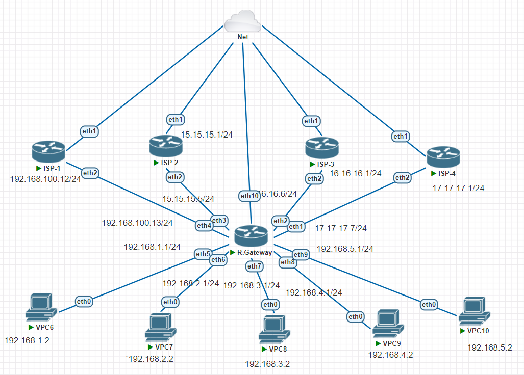
TOPOLOGY

Jalur berpindah atau putus ketika,
- Internet/logic
- Kabel/ Physical
Jalur utama atau prioritas itu distance atau AD nya lebih kecil daripada jalur backup, jalur backup memiliki distance atau AD lebih besar daripada jalur utama.
Contohnya, jalur utama memiliki distance (1) maka jalur backup harus lebih besar yaitu (2).
Pada kesempatan kali ini saya akan mensimulasikan dengan membuat 1 Router Gateway, 1 Client (VPC), dan 4 ISP yang terdiri dari,
- ISP-1 : Jalur utama memiliki distance 1
- ISP-2 : Jalur backup yang memiliki distance 2
- ISP-3 : Jalur backup yang memiliki distance 3
- ISP-4 : Jalur backup yang memiliki distance 4
Berikut konfigurasi pada ISP-1, kita seting internet gateway terlebih dahulu,
- IP Address
- DNS
- DHCP-Client
- IP Firewall NAT
Kemudian, memastikan dengan mengetes PING 8.8.8.8, ISP-1 mendapatkan internet
[admin@MikroTik] > system identity set name=ISP-1
[admin@ISP-1] > ip dhcp-client pr
Flags: X - disabled, I - invalid, D - dynamic
 #   INTERFACE           USE ADD-DEFAULT-ROUTE STATUS        ADDRESS
 0   ether1              yes yes               bound         192.168.83.192/24
[admin@ISP-1] > ip address add address=15.15.15.1/24 interface=ether2
[admin@ISP-1] > ip dns set servers=8.8.8.8
[admin@ISP-1] > ip firewall nat add chain=srcnat out-interface=ether1 action=masquerade
[admin@ISP-1] > ping 8.8.8.8
  SEQ HOST                                     SIZE TTL TIME  STATUS
    0 8.8.8.8                                    56 128 65ms
    1 8.8.8.8                                    56 128 23ms
    2 8.8.8.8                                    56 128 27ms
    sent=3 received=3 packet-loss=0% min-rtt=23ms avg-rtt=38ms max-rtt=65ms
Sama seperti sebelumnya pada ISP-1, kita seting internet gateway ISP-2 terlebih dahulu,
- IP Address
- DNS
- DHCP-Client
- IP Firewall NAT
Kemudian, memastikan dengan mengetes PING 8.8.8.8, ISP-2 mendapatkan internet
[admin@ISP-W] > system identity set name=ISP-2
[admin@ISP-2] > ip dhcp-client pr
Flags: X - disabled, I - invalid, D - dynamic
 #   INTERFACE           USE ADD-DEFAULT-ROUTE STATUS        ADDRESS
 0   ether1              yes yes               bound         192.168.83.193/24
[admin@ISP-2] > ip address add address=16.16.16.1/24 interface=ether2
[admin@ISP-2] > ip dns set servers=8.8.8.8
[admin@ISP-2] > ip firewall nat add chain=srcnat out-interface=ether1 action=masquerade
[admin@ISP-2] > ping 8.8.8.8
  SEQ HOST                                     SIZE TTL TIME  STATUS
    0 8.8.8.8                                    56 128 401ms
    1 8.8.8.8                                    56 128 40ms
    2 8.8.8.8                                    56 128 66ms
    3 8.8.8.8                                    56 128 44ms
    sent=4 received=4 packet-loss=0% min-rtt=40ms avg-rtt=137ms max-rtt=401ms
Sama seperti sebelumnya, Kita seting internet gateway ISP-3 terlebih dahulu,
- IP Address
- DNS
- DHCP-Client
- IP Firewall NAT
Kemudian, memastikan dengan mengetes PING 8.8.8.8 bahwa ISP-3 mendapatkan internet
[admin@MikroTik] > system identity set name=ISP-3
[admin@ISP-3] > ip dhcp-client pr
Flags: X - disabled, I - invalid, D - dynamic
 #   INTERFACE           USE ADD-DEFAULT-ROUTE STATUS        ADDRESS
 0   ether1              yes yes               bound         192.168.83.194/24
[admin@ISP-3] > ip address add address=17.17.17.1/24 interface=ether2
[admin@ISP-3] > ip dns set servers=8.8.8.8
[admin@ISP-3] > ip firewall nat add chain=srcnat out-interface=ether1 action=masquerade
[admin@ISP-3] > ping 8.8.8.8
  SEQ HOST                                     SIZE TTL TIME  STATUS
    0 8.8.8.8                                    56 128 89ms
    1 8.8.8.8                                    56 128 24ms
    sent=2 received=2 packet-loss=0% min-rtt=24ms avg-rtt=56ms max-rtt=89ms
Terakhir, pada ISP-4 sama seperti sebelumnya, kita men-setting terlebih dahulu,
- IP Address
- DNS
- DHCP-Client
- IP Firewall NAT
Kemudian, memastikan dengan mengetes PING 8.8.8.8 bahwa ISP-3 mendapatkan internet
[admin@MikroTik] > system identity set name=ISP-4
[admin@ISP-4] > ip dhcp-client pr
Flags: X - disabled, I - invalid, D - dynamic
 #   INTERFACE           USE ADD-DEFAULT-ROUTE STATUS        ADDRESS
 0   ether1              yes yes               bound         192.168.83.195/24
[admin@ISP-4] > ip address add address=18.18.18.1/24 interface=ether2
[admin@ISP-4] > ip dns set servers=8.8.8.8
[admin@ISP-4] > ip firewall nat  add chain=srcnat out-interface=ether1 action=masquerade
[admin@ISP-4] > ping 8.8.8.8
  SEQ HOST                                     SIZE TTL TIME  STATUS
    0 8.8.8.8                                    56 128 85ms
    1 8.8.8.8                                    56 128 30ms
    2 8.8.8.8                                    56 128 39ms
    3 8.8.8.8                                    56 128 27ms
    4 8.8.8.8                                    56 128 35ms
    sent=5 received=5 packet-loss=0% min-rtt=27ms avg-rtt=43ms max-rtt=85ms
Router Gateway
Langkah selanjutnya dalam proses ini adalah konfigurasi router gateway. Proses ini mirip dengan langkah-langkah sebelumnya, di mana kita mengatur alamat IP, DNS, dan firewall NAT. Namun, ada perbedaan penting di sini: kita perlu membuat empat NAT yang mengarah ke internet klien.
[admin@R.GW] > ip address add address=192.168.1.1/24 interface=ether5
[admin@R.GW] > ip address add address=15.15.15.5/24 interface=ether4
[admin@R.GW] > ip address add address=16.16.16.6/24 interface=ether3
[admin@R.GW] > ip address add address=17.17.17.7/24 interface=ether2
[admin@R.GW] > ip address add address=18.18.18.8/24 interface=ether1
[admin@R.GW] > ip add pr
Flags: X - disabled, I - invalid, D - dynamic
 #   ADDRESS            NETWORK         INTERFACE
 0   192.168.1.1/24     192.168.1.0     ether5
 1   15.15.15.5/24      15.15.15.0      ether4
 2   16.16.16.6/24      16.16.16.0      ether3
 3   17.17.17.7/24      17.17.17.0      ether2
 4   18.18.18.8/24      18.18.18.0      ether1
[admin@R.GW] > ip dns pr
                      servers: 8.8.8.8
              dynamic-servers:
               use-doh-server:
              verify-doh-cert: no
        allow-remote-requests: no
          max-udp-packet-size: 4096
         query-server-timeout: 2s
          query-total-timeout: 10s
       max-concurrent-queries: 100
  max-concurrent-tcp-sessions: 20
                   cache-size: 2048KiB
                cache-max-ttl: 1w
                   cache-used: 24KiB
[admin@R.GW] > ip firewall nat add chain=srcnat out-interface=ether4 action=masquerade
[admin@R.GW] > ip firewall nat add chain=srcnat out-interface=ether3 action=masquerade
[admin@R.GW] > ip firewall nat add chain=srcnat out-interface=ether2 action=masquerade
[admin@R.GW] > ip firewall nat add chain=srcnat out-interface=ether1 action=masquerade
[admin@R.GW] > ip firewall nat pr
Flags: X - disabled, I - invalid, D - dynamic
 0    chain=srcnat action=masquerade out-interface=ether4

 1    chain=srcnat action=masquerade out-interface=ether3

 2    chain=srcnat action=masquerade out-interface=ether2

 3    chain=srcnat action=masquerade out-interface=ether1
[admin@R.GW] > ping 8.8.8.8
  SEQ HOST                                     SIZE TTL TIME  STATUS
    0 8.8.8.8                                    56 127 46ms
    1 8.8.8.8                                    56 127 33ms
    sent=2 received=2 packet-loss=0% min-rtt=33ms avg-rtt=39ms max-rtt=46ms
Pada tahap ini, kita juga perlu mengonfigurasi static routing. Ini dilakukan dengan menggunakan ip route. Pada konfigurasi sebelumnya, untuk load balance, kita memasukkan semua gateway. Namun, dalam kasus fail over, kita perlu memasukkan gateway satu per satu. Konfigurasi ini perlu disesuaikan dengan distance masing-masing. Jalur utama akan memiliki distance paling kecil, yang menunjukkan prioritasnya dalam konfigurasi ini.
[admin@R.GW] > ip route add gateway=15.15.15.1 distance=1 check-gateway=ping
[admin@R.GW] > ip route add gateway=16.16.16.1 distance=2
[admin@R.GW] > ip route add gateway=17.17.17.1 distance=3
[admin@R.GW] > ip route add gateway=18.18.18.1 distance=4
[admin@R.GW] > ip route pr[admin@R.GW] > ip route pr
Flags: X - disabled, A - active, D - dynamic,
C - connect, S - static, r - rip, b - bgp, o - ospf, m - mme,
B - blackhole, U - unreachable, P - prohibit
 #      DST-ADDRESS        PREF-SRC        GATEWAY            DISTANCE
 0 A S  0.0.0.0/0                          15.15.15.1                1
 1   S  0.0.0.0/0                          16.16.16.1                2
 2   S  0.0.0.0/0                          17.17.17.1                3
 3   S  0.0.0.0/0                          18.18.18.1                4
 4 ADC  15.15.15.0/24      15.15.15.5      ether4                    0
 5 ADC  16.16.16.0/24      16.16.16.6      ether3                    0
 6 ADC  17.17.17.0/24      17.17.17.7      ether2                    0
 7 ADC  18.18.18.0/24      18.18.18.8      ether1                    0
 8 ADC  192.168.1.0/24     192.168.1.1     ether5                    0
PENGUJIAN DENGAN TRACE ROUTE
Ketika kita menjalankan perintah traceroute menuju alamat IP 8.8.8.8, suatu proses yang digunakan untuk melacak dan mencatat jalur yang diambil paket dari komputer kita ke tujuan akhirnya, link akan secara otomatis diarahkan pada jalur utama atau jalur prioritas. Jalur utama ini memiliki alamat IP 15.15.15.1. Ini berarti bahwa semua data dan paket yang kita kirimkan akan melewati jalur ini terlebih dahulu sebelum mencapai tujuan akhirnya.
[admin@R.GW] > tool traceroute address=8.8.8.8
 # ADDRESS                          LOSS SENT    LAST     AVG    BEST   WORST
 1 15.15.15.1                         0%    3   1.7ms     2.8     1.7     4.2
 2 192.168.83.2                       0%    3   3.1ms       3     2.6     3.3
 3 192.168.127.129                    0%    3   5.9ms     6.6     5.9     7.2
 4 172.17.37.233                      0%    3  32.2ms    42.8    32.2    52.6
 5 172.17.42.141                      0%    3  44.1ms    34.7    28.2    44.1
 6 172.17.42.69                       0%    3  49.6ms    50.7    49.6    52.1
 7 172.28.15.49                       0%    3  45.4ms    42.3    40.7    45.4
 8 10.47.4.21                        50%    3 timeout    34.8    34.8    34.8
 9 8.8.8.8                            0%    2  50.1ms    45.1      40    50.1
Jika kita melakukan penonaktifan atau mematikan jalur utama yang biasanya kita gunakan, akan terjadi perubahan secara otomatis di mana Internet Service Provider (ISP) akan langsung berpindah ke jalur backup kedua. Jalur backup kedua ini memiliki alamat IP yang berbeda, yaitu 16.16.16.1, dan akan menjadi jalur utama yang baru jika jalur utama sebelumnya mengalami gangguan atau dimatikan.
[admin@R.GW] > interface pr
Flags: D - dynamic, X - disabled, R - running, S - slave
 #     NAME                                TYPE       ACTUAL-MTU L2MTU
 0  R  ether1                              ether            1500
 1  R  ether2                              ether            1500
 2  R  ether3                              ether            1500
 3  R  ether4                              ether            1500
 4  R  ether5                              ether            1500
[admin@R.GW] > interface disable 3
[admin@R.GW] > interface pr
Flags: D - dynamic, X - disabled, R - running, S - slave
 #     NAME                                TYPE       ACTUAL-MTU L2MTU
 0  R  ether1                              ether            1500
 1  R  ether2                              ether            1500
 2  R  ether3                              ether            1500
 3  X  ether4                              ether            1500
 4  R  ether5                              ether            1500
[admin@R.GW] > ip route pr detail
Flags: X - disabled, A - active, D - dynamic,
C - connect, S - static, r - rip, b - bgp, o - ospf, m - mme,
B - blackhole, U - unreachable, P - prohibit
 0   S  dst-address=0.0.0.0/0 gateway=15.15.15.1
        gateway-status=15.15.15.1 unreachable distance=1 scope=30
        target-scope=10

 1 A S  dst-address=0.0.0.0/0 gateway=16.16.16.1
        gateway-status=16.16.16.1 reachable via  ether3 distance=2 scope=30
        target-scope=10

 2   S  dst-address=0.0.0.0/0 gateway=17.17.17.1
        gateway-status=17.17.17.1 reachable via  ether2 distance=3 scope=30
        target-scope=10

 3   S  dst-address=0.0.0.0/0 gateway=18.18.18.1
        gateway-status=18.18.18.1 reachable via  ether1 distance=4 scope=30
        target-scope=10

 4 ADC  dst-address=16.16.16.0/24 pref-src=16.16.16.6 gateway=ether3
        gateway-status=ether3 reachable distance=0 scope=10

 5 ADC  dst-address=17.17.17.0/24 pref-src=17.17.17.7 gateway=ether2
[admin@R.GW] > tool traceroute address=8.8.8.8
 # ADDRESS                          LOSS SENT    LAST     AVG    BEST   WORST
 1 16.16.16.1                         0%    3   1.8ms     4.7     1.8     6.4
 2 192.168.83.2                       0%    3   2.6ms     5.3     2.6      10
 3 192.168.127.129                    0%    3   6.2ms     6.4     5.3     7.8
 4 172.17.37.233                      0%    3  28.2ms      39    28.2    50.6
 5 172.17.42.141                      0%    3  45.1ms    37.5    27.5    45.1
 6 172.17.42.69                       0%    3  41.2ms    42.5    39.3      47
 7 172.28.15.49                       0%    3  39.4ms      42    39.4    44.4
 8                                  100%    3 timeout
 9 8.8.8.8                            0%    2  36.1ms    46.3    36.1    56.4
Selanjutnya, kita juga harus melakukan pengecekan pada client VPC untuk memastikan apakah trace juga telah berpindah sesuai dengan yang diharapkan.
Setelah melakukan konfigurasi dan pengecekan pada Router Gateway, langkah selanjutnya adalah melakukan verifikasi pada sisi klien. Pada kasus ini, kita akan menggunakan Virtual PC Simulator (VPCS) sebagai klien dan melakukan pengecekan apakah paket data yang dikirim melalui gateway sudah berpindah atau belum.
Pertama, kita harus menetapkan alamat IP dan gateway pada VPCS kita. Dalam hal ini, kita akan membuat alamat IP klien menjadi 192.168.1.2 dengan gateway 192.168.1.1, yang merupakan alamat IP dari router gateway kita.
VPCS> ip 192.168.1.2/24 192.168.1.1
Checking for duplicate address...
PC1 : 192.168.1.2 255.255.255.0 gateway 192.168.1.1
Kemudian, kita menetapkan DNS server pada klien. Di sini kita akan menggunakan Google Public DNS, yaitu 8.8.8.8.
VPCS> ip dns 8.8.8.8
Setelah itu, kita coba melakukan ping ke DNS server untuk memastikan koneksi internet kita berfungsi dengan baik.
VPCS> ping 8.8.8.8

84 bytes from 8.8.8.8 icmp_seq=1 ttl=126 time=51.563 ms
84 bytes from 8.8.8.8 icmp_seq=2 ttl=126 time=49.445 ms
84 bytes from 8.8.8.8 icmp_seq=3 ttl=126 time=38.499 ms
84 bytes from 8.8.8.8 icmp_seq=4 ttl=126 time=31.777 ms
84 bytes from 8.8.8.8 icmp_seq=5 ttl=126 time=30.841 ms
Terakhir, kita jalankan perintah trace untuk memastikan paket data mengikuti jalur yang telah kita konfigurasi. Jika konfigurasi kita benar, maka jalur yang ditampilkan haruslah jalur yang kita harapkan.
VPCS> trace 8.8.8.8
trace to 8.8.8.8, 8 hops max, press Ctrl+C to stop
 1   192.168.1.1   5.498 ms  1.589 ms  2.588 ms
 2   16.16.16.1   19.008 ms  5.090 ms  4.259 ms
 3   192.168.83.2   8.557 ms  8.611 ms  4.432 ms
 4     *  *  *
 5     *  *  *
 6     *  *  *
 7     *  *  *
 8     *  *  *
Dari hasil trace di atas, kita bisa melihat bahwa paket data sudah berhasil melewati gateway dengan alamat IP 16.16.16.1, yang merupakan gateway kedua kita. Ini menunjukkan bahwa konfigurasi failover kita telah berhasil dan client VPC sudah bisa berpindah dari jalur utama ke jalur kedua ketika jalur utama mengalami gangguan.
Ketika kita melakukan perintah ping 8.8.8.8 -t, terjadi sebuah situasi menarik. Jika kita mematikan interface pada router gateway, akan ada di mana proses ping kita tidak mendapatkan respon, atau timeout. Di sini, kita bisa melihat bahwa router gateway sedang melakukan proses pergantian jalur. Proses ini penting untuk memastikan bahwa data yang kita kirim dapat mencapai tujuan. Setelah proses pergantian jalur selesai, status ping kita akan kembali normal, dan kita akan mendapatkan respon reply dari server tujuan.
VPCS> ping 8.8.8.8 -t

84 bytes from 8.8.8.8 icmp_seq=1 ttl=126 time=123.755 ms
84 bytes from 8.8.8.8 icmp_seq=2 ttl=126 time=52.650 ms
84 bytes from 8.8.8.8 icmp_seq=3 ttl=126 time=50.295 ms
84 bytes from 8.8.8.8 icmp_seq=4 ttl=126 time=50.963 ms
84 bytes from 8.8.8.8 icmp_seq=5 ttl=126 time=27.103 ms
84 bytes from 8.8.8.8 icmp_seq=6 ttl=126 time=33.424 ms
84 bytes from 8.8.8.8 icmp_seq=7 ttl=126 time=29.335 ms
84 bytes from 8.8.8.8 icmp_seq=8 ttl=126 time=32.550 ms
84 bytes from 8.8.8.8 icmp_seq=9 ttl=126 time=28.844 ms
84 bytes from 8.8.8.8 icmp_seq=10 ttl=126 time=35.732 ms
84 bytes from 8.8.8.8 icmp_seq=11 ttl=126 time=35.208 ms
84 bytes from 8.8.8.8 icmp_seq=12 ttl=126 time=40.206 ms
84 bytes from 8.8.8.8 icmp_seq=13 ttl=126 time=34.214 ms
84 bytes from 8.8.8.8 icmp_seq=14 ttl=126 time=30.389 ms
84 bytes from 8.8.8.8 icmp_seq=15 ttl=126 time=39.099 ms
84 bytes from 8.8.8.8 icmp_seq=16 ttl=126 time=29.190 ms
84 bytes from 8.8.8.8 icmp_seq=17 ttl=126 time=29.821 ms
84 bytes from 8.8.8.8 icmp_seq=18 ttl=126 time=27.931 ms
84 bytes from 8.8.8.8 icmp_seq=19 ttl=126 time=31.934 ms
84 bytes from 8.8.8.8 icmp_seq=20 ttl=126 time=28.941 ms
84 bytes from 8.8.8.8 icmp_seq=21 ttl=126 time=28.650 ms
84 bytes from 8.8.8.8 icmp_seq=22 ttl=126 time=34.129 ms
84 bytes from 8.8.8.8 icmp_seq=23 ttl=126 time=28.819 ms
84 bytes from 8.8.8.8 icmp_seq=24 ttl=126 time=48.133 ms
84 bytes from 8.8.8.8 icmp_seq=25 ttl=126 time=52.502 ms
84 bytes from 8.8.8.8 icmp_seq=26 ttl=126 time=27.321 ms
84 bytes from 8.8.8.8 icmp_seq=27 ttl=126 time=30.149 ms
84 bytes from 8.8.8.8 icmp_seq=28 ttl=126 time=34.314 ms
84 bytes from 8.8.8.8 icmp_seq=29 ttl=126 time=37.029 ms
84 bytes from 8.8.8.8 icmp_seq=30 ttl=126 time=37.794 ms
84 bytes from 8.8.8.8 icmp_seq=31 ttl=126 time=25.411 ms
84 bytes from 8.8.8.8 icmp_seq=32 ttl=126 time=27.619 ms
84 bytes from 8.8.8.8 icmp_seq=33 ttl=126 time=35.410 ms
84 bytes from 8.8.8.8 icmp_seq=34 ttl=126 time=31.603 ms
84 bytes from 8.8.8.8 icmp_seq=35 ttl=126 time=27.129 ms
84 bytes from 8.8.8.8 icmp_seq=36 ttl=126 time=29.375 ms
84 bytes from 8.8.8.8 icmp_seq=37 ttl=126 time=45.334 ms
84 bytes from 8.8.8.8 icmp_seq=38 ttl=126 time=29.115 ms
84 bytes from 8.8.8.8 icmp_seq=39 ttl=126 time=33.359 ms
84 bytes from 8.8.8.8 icmp_seq=40 ttl=126 time=36.451 ms
84 bytes from 8.8.8.8 icmp_seq=41 ttl=126 time=37.045 ms
84 bytes from 8.8.8.8 icmp_seq=42 ttl=126 time=34.846 ms
84 bytes from 8.8.8.8 icmp_seq=43 ttl=126 time=33.482 ms
84 bytes from 8.8.8.8 icmp_seq=44 ttl=126 time=31.117 ms
84 bytes from 8.8.8.8 icmp_seq=45 ttl=126 time=27.835 ms
84 bytes from 8.8.8.8 icmp_seq=46 ttl=126 time=36.811 ms
84 bytes from 8.8.8.8 icmp_seq=47 ttl=126 time=38.902 ms
84 bytes from 8.8.8.8 icmp_seq=48 ttl=126 time=57.951 ms
8.8.8.8 icmp_seq=49 timeout
84 bytes from 8.8.8.8 icmp_seq=50 ttl=126 time=85.434 ms
84 bytes from 8.8.8.8 icmp_seq=51 ttl=126 time=50.355 ms
84 bytes from 8.8.8.8 icmp_seq=52 ttl=126 time=306.208 ms
84 bytes from 8.8.8.8 icmp_seq=53 ttl=126 time=60.254 ms
84 bytes from 8.8.8.8 icmp_seq=54 ttl=126 time=35.152 ms
84 bytes from 8.8.8.8 icmp_seq=55 ttl=126 time=34.493 ms
84 bytes from 8.8.8.8 icmp_seq=56 ttl=126 time=38.589 ms
84 bytes from 8.8.8.8 icmp_seq=57 ttl=126 time=29.826 ms
84 bytes from 8.8.8.8 icmp_seq=58 ttl=126 time=30.140 ms
84 bytes from 8.8.8.8 icmp_seq=59 ttl=126 time=27.410 ms
84 bytes from 8.8.8.8 icmp_seq=60 ttl=126 time=27.041 ms
84 bytes from 8.8.8.8 icmp_seq=61 ttl=126 time=34.139 ms
84 bytes from 8.8.8.8 icmp_seq=62 ttl=126 time=30.313 ms
84 bytes from 8.8.8.8 icmp_seq=63 ttl=126 time=35.589 ms
84 bytes from 8.8.8.8 icmp_seq=64 ttl=126 time=29.685 ms
84 bytes from 8.8.8.8 icmp_seq=65 ttl=126 time=27.425 ms
84 bytes from 8.8.8.8 icmp_seq=66 ttl=126 time=33.934 ms
84 bytes from 8.8.8.8 icmp_seq=67 ttl=126 time=37.594 ms
84 bytes from 8.8.8.8 icmp_seq=68 ttl=126 time=49.995 ms
84 bytes from 8.8.8.8 icmp_seq=69 ttl=126 time=34.830 ms
84 bytes from 8.8.8.8 icmp_seq=70 ttl=126 time=28.726 ms
84 bytes from 8.8.8.8 icmp_seq=71 ttl=126 time=31.260 ms
84 bytes from 8.8.8.8 icmp_seq=72 ttl=126 time=49.041 ms
84 bytes from 8.8.8.8 icmp_seq=73 ttl=126 time=35.885 ms
84 bytes from 8.8.8.8 icmp_seq=74 ttl=126 time=34.514 ms
^C
VPCS> trace 8.8.8.8
trace to 8.8.8.8, 8 hops max, press Ctrl+C to stop
 1   192.168.1.1   1.101 ms  0.962 ms  1.011 ms
 2   16.16.16.1   2.357 ms  2.407 ms  2.329 ms
 3   192.168.83.2   6.069 ms  3.436 ms  3.353 ms
 4     *  *  *
 5     *  *  *
^C 6
Jika kita telah menjalankan beberapa langkah yang telah dijelaskan diatas, maka kita telah berhasil melakukan failover dengan metode pengecekan gateway. Proses ini adalah bagian penting dari menjaga ketersediaan jaringan dan memastikan bahwa layanan tetap berjalan dengan lancar meskipun terjadi masalah. Dengan mengecek gateway, kita bisa mengarahkan lalu lintas ke jalur lain jika jalur utama mengalami gangguan, sehingga layanan tetap dapat berjalan tanpa gangguan.

Comments
Post a Comment